So I decided I wanted to build a lighthouse. After some thought, it occurred to me that since I always enjoy visiting Provincetown, whether by land or by sea, building one of the lighthouses in Provincetown would be a fun project.
There are three lighthouses in Provincetown, Race Point Light, Wood End Light, and Long Point Light.
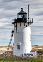
Race Point Light 
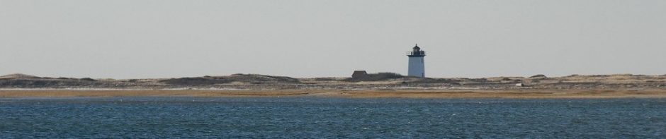
Wood End Light 
Long Point Light
The locations of these three lights can be seen on the nautical chart below. A lighthouse (or other lighted navigational aid) is indicated by a black dot and a purple teardrop shape (![]() ). Race Point Light is at the upper left of the picture (flashes white once every 10 seconds). Wood End Light is at the bottom of the picture (flashes red once every 10 seconds). And Long Point Light is to the right of Wood End (it has green light that occults (turns off) once every 4 seconds).
). Race Point Light is at the upper left of the picture (flashes white once every 10 seconds). Wood End Light is at the bottom of the picture (flashes red once every 10 seconds). And Long Point Light is to the right of Wood End (it has green light that occults (turns off) once every 4 seconds).

Race Point Light is round, and I wasn’t quite sure how to construct that. Wood End and Long Point lights are almost identical, so I picked Wood End, which is also a bit easier to get to by foot.
The first step in the project was drawing up plans. This required knowing the dimensions of the actual lighthouse. There is a dyke (erroneously called “The Jetty” by some of the locals) that leads from the Provincetown Inn out to Wood End. If the tide is low enough, you can walk all the way out there. In September 2019, I went out there with a tape measure and a camera, and took a bunch of pictures and measurements.

Northwest Corner 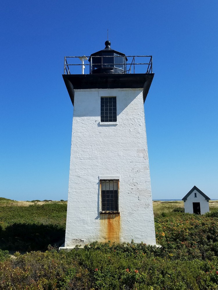
West Side 
South Side 
East Side
And, of course I took a selfie…

Based on the photos and my measurements, I estimate that the lighthouse is 41 feet high, including the lightning rod at the top of the finial. I opted for a 1:12 scale model, so that will make my model 3 feet, 5 inches tall.
I will put some plans and pictures below. Over the next few months, I’ll continue to add updates, as well as explanations of many of the pictures.
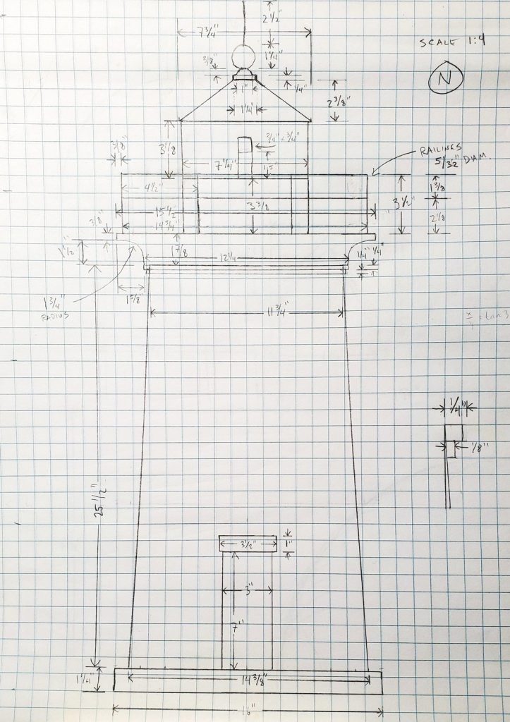
1:4 Scale Drawing of North side of Lighthouse